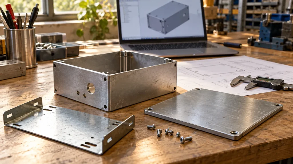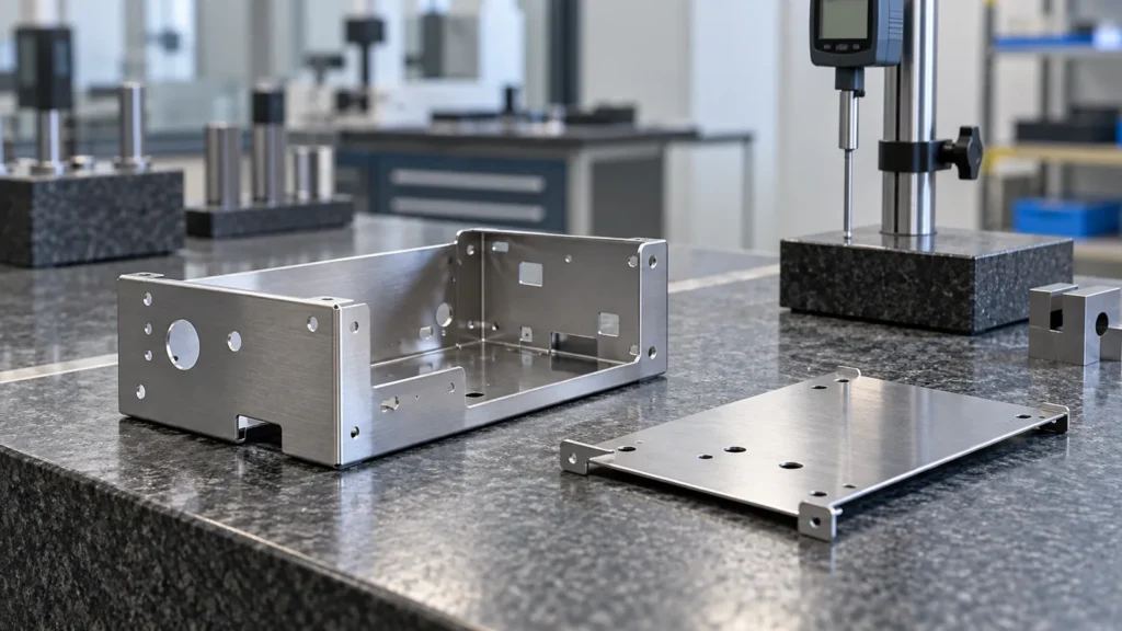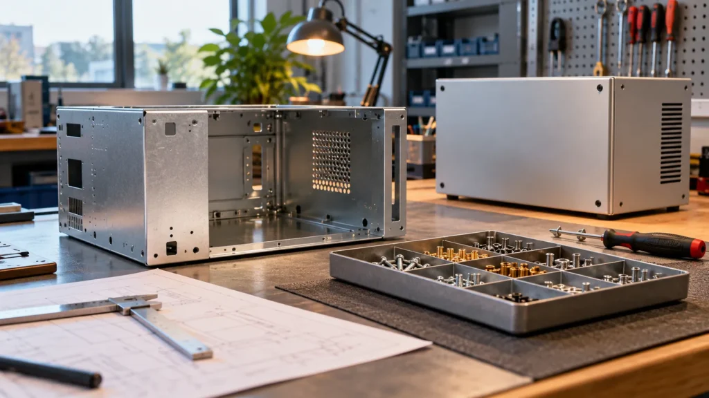
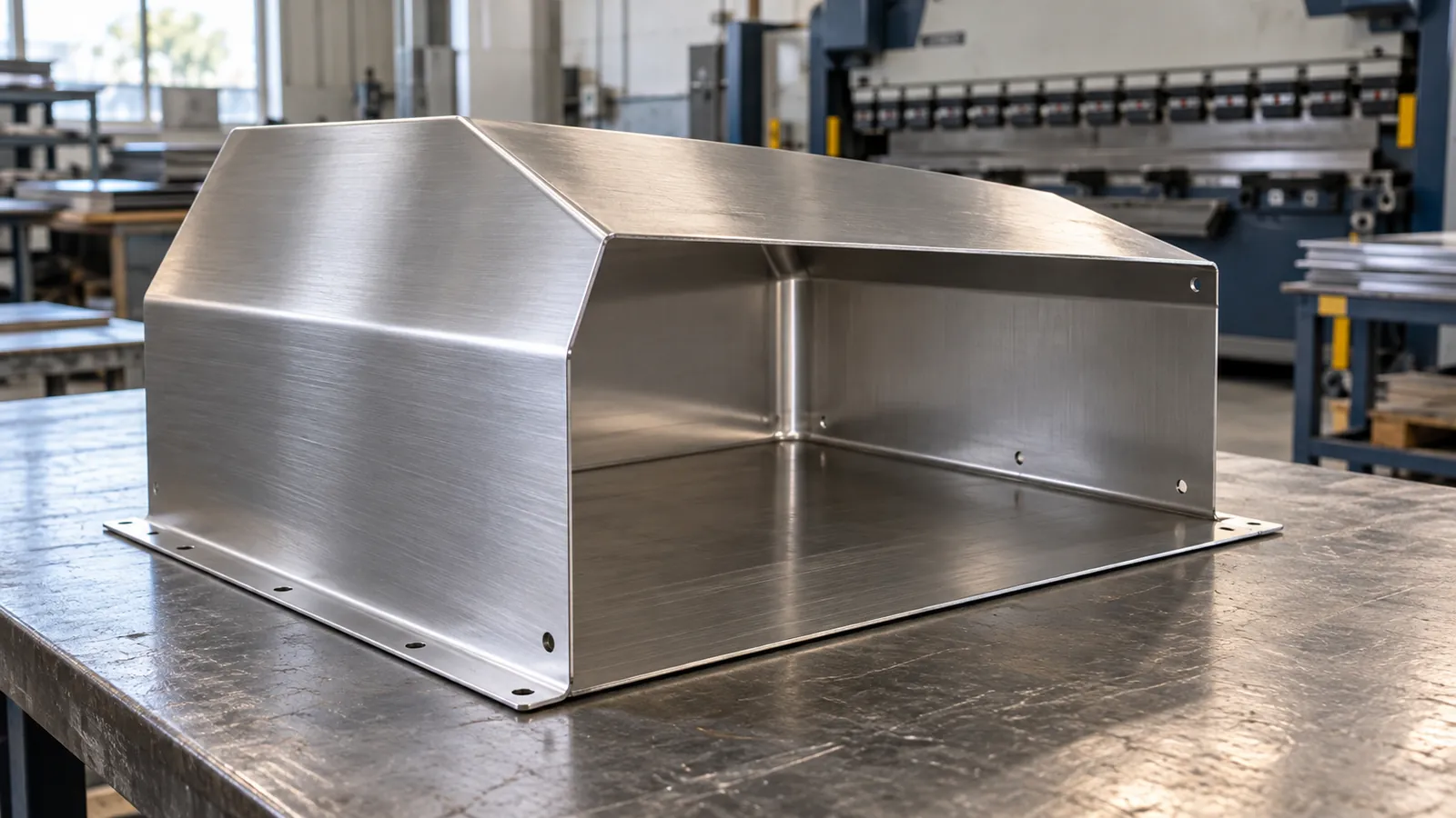
Sheet metal bend radius usually means the radius on the inside of a formed corner. It affects the space around the bend, the material’s ability to form and the flat length needed to produce the finished part. It should be chosen with the material and manufacturing route before the flat pattern is treated as final.
A radius that looks tidy in CAD may not match the available tooling or leave room for a mating component. A calculator can help establish dimensions once the inputs are appropriate. It cannot decide, on its own, whether the selected sheet will form successfully.
Inside radius, outside radius and thickness
Take a section through a simple bent strip. The inside surface forms the smaller curve; the outside surface follows a larger one. For an idealized bend with unchanged thickness, the outside radius equals the inside radius plus the thickness. Real forming can change local thickness, so use the relationship as a geometric description rather than an inspection guarantee.
Identify which radius the drawing specifies. Also state material thickness in clear units. A radius of 2 mm and a thickness of 1.5 mm make a different forming question from a radius of 2 mm in 3 mm sheet.
The ratio R/t is a convenient way to discuss that relationship, where R is the inside radius and t is thickness. It is not a material specification. Two sheets with the same thickness can have different forming limits because their alloy, condition or rolling direction differs.
Protolabs’ bend-radius guidance identifies material, thickness, bend angle, forming method and K-factor as connected inputs. That is why a radius copied from an unrelated part may give an unsuitable starting point. Protolabs: sheet metal bend-radius guidelines
There is no single minimum radius for every sheet
A minimum-radius decision needs the actual alloy and condition, thickness, bend direction and proposed tooling. Tightening the curve increases the forming demand on the outer surface. A sharp-looking corner in a model does not establish that the selected material can tolerate it.
Do not treat a familiar rule of thumb as approval for every material. A supplier’s published radius table may describe its particular stock, tools and process. Confirm whether that combination applies to the part being ordered.
Also distinguish a minimum that can be formed from the radius that is sensible for the product. A slightly larger radius may suit standard tooling and still provide all the clearance the assembly needs. A smaller one may be necessary for a real interface, but that requirement should be made explicit.
During a bending and stamping review, show the part that sits beside the corner. The manufacturer can then assess the forming requirement while the designer checks the space the resulting shape occupies.
What a bend-allowance calculation actually does
The inside of a bend compresses while the outside stretches. The neutral axis is the idealized layer whose length remains unchanged through the bend. K-factor locates that layer through the thickness and is used in calculating bend allowance.
For a simple calculation with angle in degrees:
Bend allowance = (π × bend angle ÷ 180) × (inside radius + K × thickness)
Bend allowance is the neutral-axis arc length through the curved region. Bend deduction is a different quantity: it lets you work from defined outside flange dimensions back to the flat length. SendCutSend explains both calculations and the need to use the appropriate material and bending values. SendCutSend: bend allowance and bend deduction
Consider one illustrative 90-degree bend with these assumed inputs:
| Input | Assumed value |
|---|---|
| Sheet thickness, t | 1.50 mm |
| Inside radius, R | 2.00 mm |
| K-factor | 0.40 |
| Outside flange dimensions to the theoretical sharp intersection | 30.00 mm and 40.00 mm |
The bend allowance is (π/2) × (2.00 + 0.40 × 1.50), or approximately 4.08 mm.
For this 90-degree example, bend deduction is 2 × (R + t) minus bend allowance: 7.00 − 4.08 = 2.92 mm. The resulting calculated flat length is 30.00 + 40.00 − 2.92 = 67.08 mm.
Those values illustrate the method. The assumed K-factor and radius are not approved production settings. Dimensions taken from tangent points would require a different bookkeeping approach from the outside flange dimensions used here.
Check what happens beside the bend
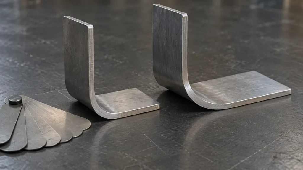
The curved region occupies space that a sharp corner does not. A square-edged rail may contact an internal bend before it reaches the intended seat. A return flange may leave less room for a connector than the outside envelope suggests.
Review the completed section with its mating components. For a U-shaped part, check both straight-leg clearance and the space near the bridge. The same principle applies to a cover that wraps around a frame or a panel that sits against a folded support.
Nearby holes and slots also need attention. A feature too close to the deforming region may change shape during bending. The usable separation depends on the feature, material and tooling; it should not be guessed from one broad rule.
When using a supplier’s spacing guidance, check its reference. Distance from a hole center to a bend line, to a tangent point and to the edge of a bend-allowance region are different dimensions. Copying the number while changing its reference can defeat the purpose of the rule.
Reliefs at interrupted bends need the same care. Their shape should allow the intended forming operation while preserving the function and appearance of the completed corner.
Agree who controls the production flat pattern
A sheet-metal model may unfold successfully using default settings while producing a flat pattern that differs from the fabricator’s established process. The software has performed the calculation it was given; the inputs may still be wrong for the intended production route.
Agree whether the customer supplies the production flat pattern or the manufacturer develops it from the approved formed geometry. If both a DXF and a formed model are provided, identify their roles and resolve any disagreement before cutting.
Do not quietly alter one file while leaving the other at its previous revision. A corrected flat length needs to remain connected to the intended finished dimensions. ZhenPai’s cutting and punching service and forming review should work from that same agreed release.
For a family of parts, consistent radii can simplify planning where the design permits them. Standardizing should follow the actual tooling and functional needs, rather than forcing unlike materials into one arbitrary CAD setting.
Let the first formed sample check the assumptions
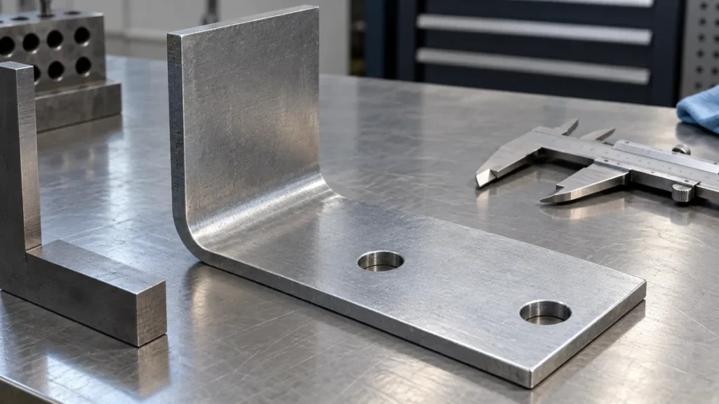
Inspect the sample’s finished angle, important flange dimensions and relevant radius using agreed methods. Also check its fit with the mating component. A radius measurement alone will not reveal every positioning or assembly issue.
If the sample differs from the intended geometry, investigate the material, forming setup and flat-pattern assumptions together. Keep any approved change traceable to a revision or process record so the next batch does not return to an obsolete calculation.
Discuss the required records during the quality-control review. When sending ZhenPai a bent-part enquiry, include the alloy and condition, thickness, formed model, critical interfaces and expected quantity. Those inputs make a bend-radius decision useful to both the drawing and the shop floor.