Threaded inserts for sheet metal solve a familiar assembly problem: a panel needs a reusable screw connection, but the material does not provide enough depth for a suitable tapped thread. The difficulty usually appears when someone needs to remove a cover. A loose nut drops into the cabinet, a screw will not tighten, or a fastening point sits beyond the reach of a wrench.
Choosing an insert takes more than matching the screw size. The panel material, installation access, hole geometry and service requirements all influence whether the connection will work. A thread that fits on the drawing can still be awkward to install or impossible to repair after the surrounding parts are assembled.
Start With the Joint You Need to Build
Before choosing a hardware family, describe the fastening point. Is it holding a removable lid, supporting a mounting plate or attaching a bracket that stays in place? Will a technician remove the screw regularly? Can the installer reach the back of the panel?
These questions separate different problems that are often grouped under the same phrase. A cover needs repeatable access. A mounting plate needs a defined position. A small electronics assembly may need spacing between components. The same nominal thread can appear in all three, but the surrounding hardware and inspection requirements will differ.
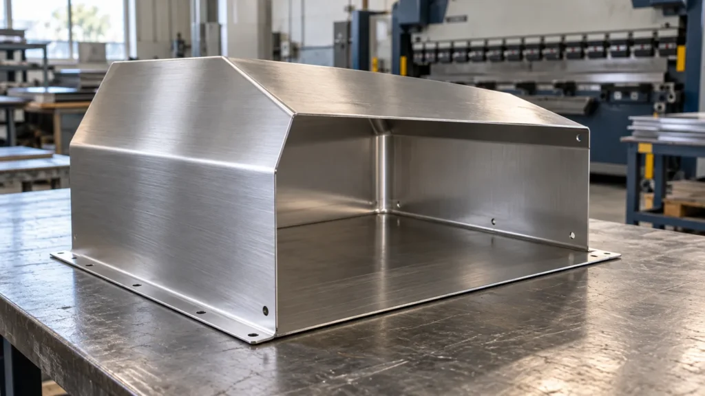
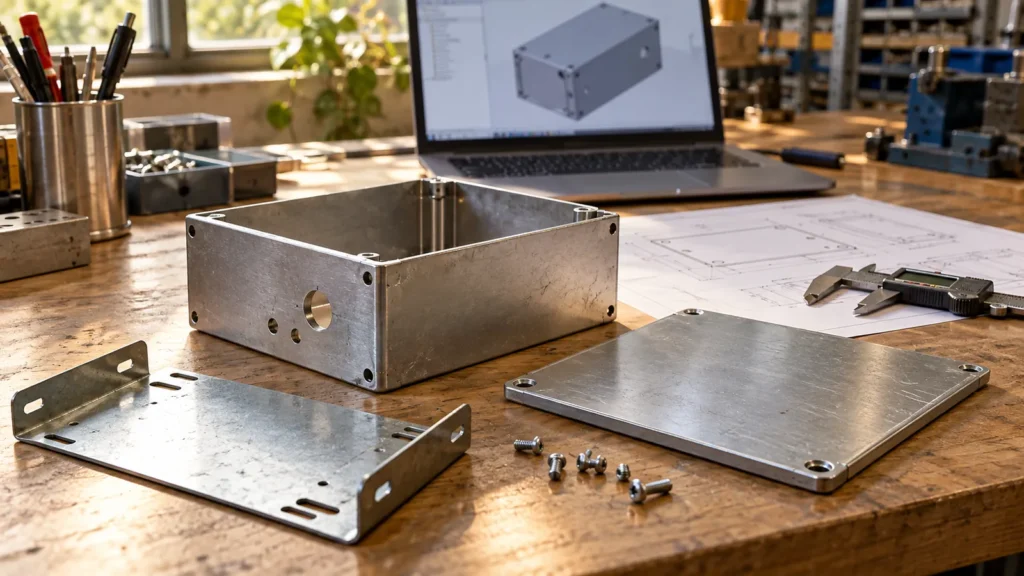
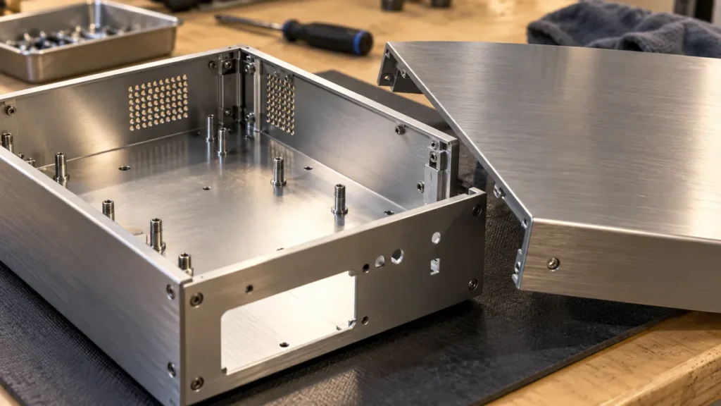
Consider a hypothetical folded enclosure with a removable top cover and four fastening points. If the nuts must be held from inside the enclosure, every service visit may require access to a second area of the assembly. A fixed threaded feature could make the lid easier to remove. That advantage disappears, however, if its projection collides with an internal component or the fastening location cannot be reached during installation.
Review the full joint in the assembled model. The screw, insert, cover, chassis and tool all need space.
Self Clinching Nuts and Rivet Nuts Address Different Access Problems
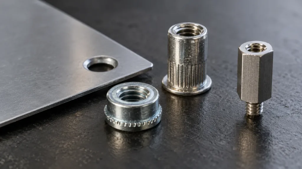
Self clinching nuts are pressed into prepared holes in compatible sheet material. Material around the hole flows into the fastener’s retention feature. The operation needs suitable support and access for the installation tooling. PennEngineering explains that sheet thickness, hardness and hole preparation affect the connection, and that hardware intended for stainless steel requires particular attention to material compatibility. PennEngineering fastener handbook
A rivet nut is installed by deforming its body to retain it in the panel. It can suit a location where installation is possible from one side. That makes it worth considering for a closed section or an assembly that no longer provides access behind the sheet.
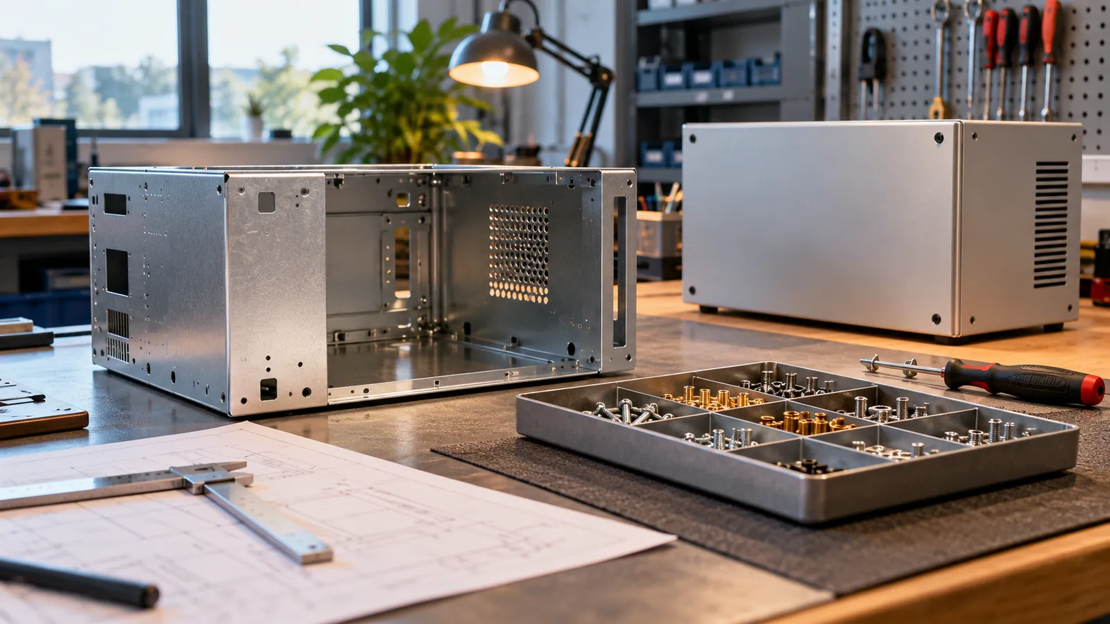
The term threaded insert does not mean that these families are interchangeable. They can require different holes, installation equipment and clearances. One may sit almost flush on a panel face while another introduces a flange or a larger projection behind it. Substituting hardware without reviewing the joint can change the fit of the cover or the clearance to nearby parts.
An early conversation with the fabricator is useful here. Describe the access problem first, then review suitable hardware rather than selecting a catalogue item solely from its thread size.
Match the Hardware to the Actual Panel
The material callout should identify the alloy or grade and the specified thickness. A description such as thin stainless steel leaves too much open. The hardware supplier’s data should then be checked against the material that will actually be purchased and formed.
For a rivet nut, the panel or material stack needs to fall within the chosen product’s grip range. STANLEY Engineered Fastening’s selection guide also calls for checking hole size, body shape and corrosion requirements. These are product specific selection details, not dimensions that can be copied from another enclosure. Blind rivet nut selection guide
If two sheets are clamped together at the fastening point, review that stack rather than checking only the outer sheet. Include any layers that affect installation or seating. A change in material thickness should trigger a hardware review even when the screw size remains the same.
Coatings also deserve attention. The installation sequence, permitted coating in the hole and masking requirements should follow the selected hardware’s instructions. Do not assume that the same sequence suits every insert family. Agree on it before the parts move through fabrication and finishing.
Leave Room for Installation and Assembly
A threaded feature may fit in a flat pattern and still become inaccessible after bending. Check the installation sequence against the formed geometry. A short return flange, a deep sidewall or an adjacent fastening point can limit how the panel is supported in the tooling.
The hardware drawing matters as much as the panel drawing. Review the specified edge distance, the area needed for installation tools and the space around nearby bends. Use the manufacturer’s requirements for the particular part number. A rule borrowed from a different insert or sheet thickness is a poor substitute.
Assembly access is a separate check. Model the tool used to tighten the mating screw, or at least reserve a realistic tool envelope. A screw that can be started in the thread by hand may still be difficult to tighten once a cable tray or another panel is in place.
Discuss these locations during the bending and stamping review. Moving a fastening point while the design is open is usually simpler than changing a completed panel.
Choose the Screw Alongside the Insert
It is easy to treat the screw as an item to buy later. That can leave the joint unfinished. Screw length depends on the cover, washers if specified, the available thread and the space behind the insert. A longer screw may contact an internal part; a shorter one may not provide the intended engagement.
For a removable cover, review the complete fastening arrangement in both its installed and service positions. Check whether the screw remains captive, whether the technician has a place to put loose hardware and whether the cover can be removed without disturbing another assembly.
Keep screw and insert specifications together in the bill of materials. If a supplier proposes a substitute, review the body, flange, installation requirements and joint performance as well as the thread. Matching M4 or M5 is only the beginning of that comparison.
Define What the Sample Must Demonstrate
A first sample should answer the questions that matter to the joint. Can the specified screw be installed without cross threading? Does the cover seat correctly? Can the required tool reach the fastening point? Does anything contact the screw or insert on the inside of the enclosure?
Where retention or tightening performance is important, agree on suitable tests, acceptance criteria and sample quantities with the responsible engineering team and hardware supplier. Looking at an installed insert does not establish its load capability. A successful finger tight assembly does not establish resistance to rotation in service.
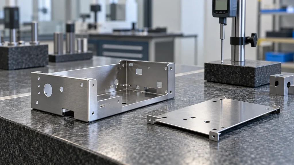
The quality control plan should identify which checks are visual, which are dimensional and which require a performance test. Record the material, hardware part number and installation method used for the approved sample. Otherwise, a later change can look harmless while altering the joint that was originally accepted.
Put the Hardware Details in the Drawing Package
The release package should state the hardware part number or an agreed equivalent specification, thread size, installation side and quantity. Hole information needs to be consistent with that selection. Mark any fastening points that require special inspection or particular clearance to internal components.
Include an assembly view when the installation side is not obvious. If only one face is cosmetic, identify it. If the cover must sit flush, show the mating surfaces and acceptable finished fit. These notes help keep purchasing, fabrication and final assembly aligned.
An enclosure that uses two insert families needs more than a general note saying install threaded hardware. Identify where each family belongs. Similar looking fastening points should not force an assembler to guess which part goes where.
For a new OEM enclosure, send the formed model, panel drawing and proposed hardware list together. ZhenPai can review the mechanical design, 3D model and manufacturing requirements with you. Send your drawings for review and identify the covers, mounting plates and fastening points that matter most to the assembly.