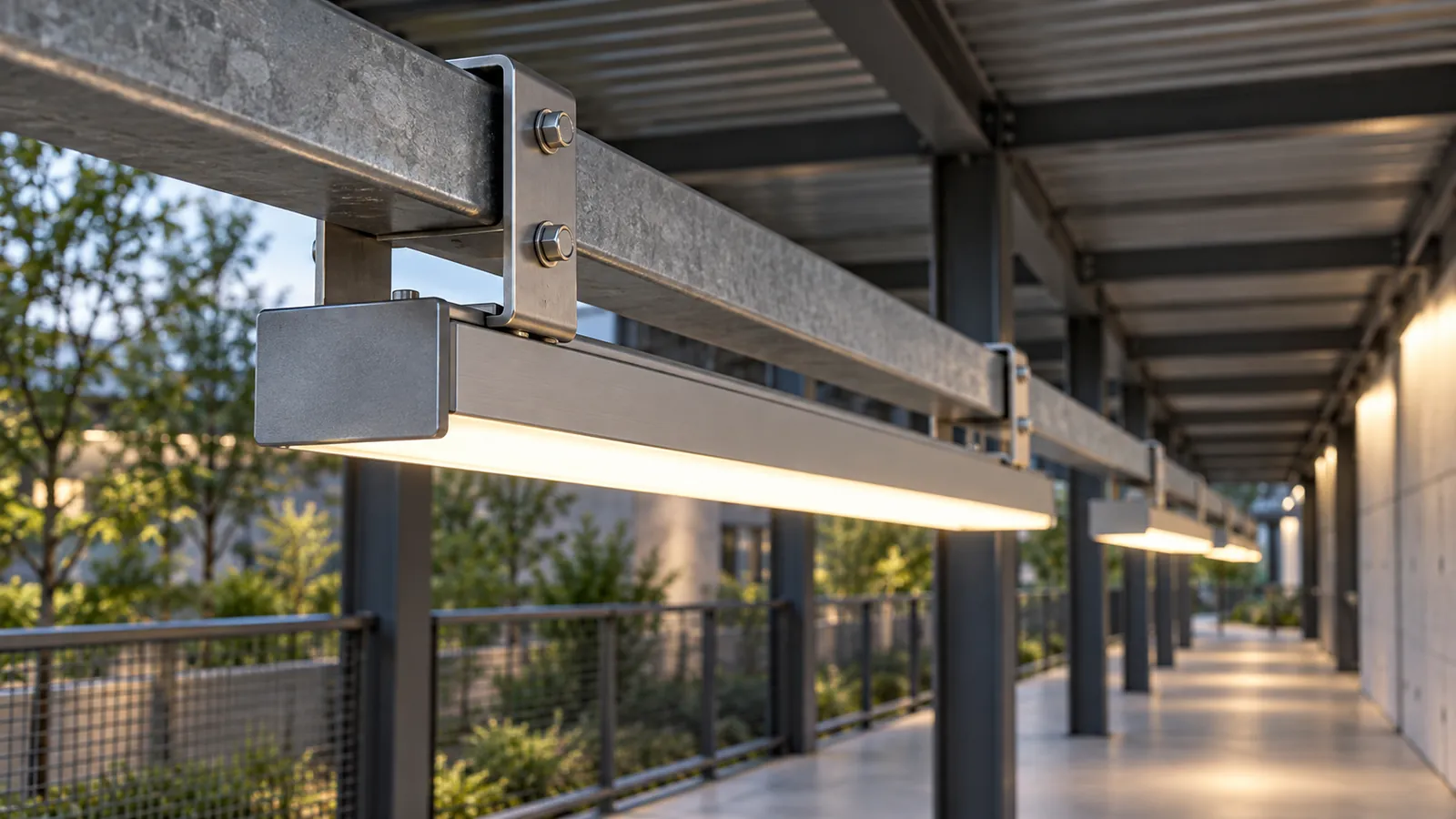
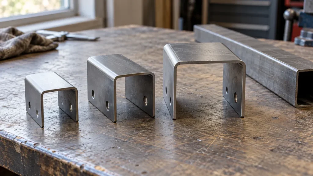
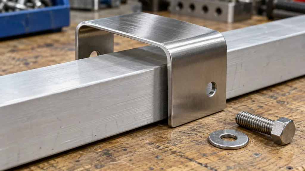
Metal U brackets have a bridge and two legs that surround, support or locate another component. The outline is simple; the fit depends on the space between those legs, the curved corners and the position of the fastening holes. Buying by outside width alone can leave a bracket that looks right and will not slide over its mating part.
For a standard connection, a stock bracket may be perfectly adequate. A custom part becomes useful when the rail size, attachment pattern, available space or finished appearance calls for a different geometry. Establish those needs before choosing the material thickness.
What needs to fit inside it?
Start with a section through the assembled connection. Show the bracket and the member it surrounds, including any coating, protective pad or other layer between them. If the bracket slides into position from one end, include that insertion path as well.
U-shaped fittings appear in quite different products. School Fix, for example, supplies them for attaching desk and seating surfaces to metal tubing. That illustrates the general connection principle, but a bracket intended for a light housing, an equipment rail or a heavier support needs its own geometry and performance requirements. School Fix: U-shaped desk brackets
Do not confuse a formed U bracket with a threaded U-bolt. They can surround similar members while providing different contact surfaces and fastening arrangements. A drawing or simple section view prevents a purchasing description from hiding that difference.
For a custom version, ZhenPai’s stamped and bent metal brackets provide a relevant starting point. Send the mating member with the bracket detail so the connection can be reviewed together.
Inside width is usually the first useful dimension
Across two parallel straight legs of uniform thickness, the bare-metal inside width equals the bare-metal outside width minus twice the sheet thickness. That relationship describes the straight section; it does not describe the usable space within the rounded corners.
Here is an illustrative clearance calculation:
| Item | Example value |
|---|---|
| Bare bracket outside width | 44.00 mm |
| Sheet thickness | 2.00 mm |
| Bare bracket inside width across straight legs | 40.00 mm |
| Finished mating rail width | 39.60 mm |
| Total clearance before coating the bracket | 0.40 mm |
If the bracket then receives an assumed 0.08 mm coating on each inner face, its internal width becomes 39.84 mm. The remaining total clearance is 0.24 mm, or 0.12 mm per side when centered. These assumed dimensions explain the arithmetic; they are not recommended coating values or an approved fit.
Manufacturing variation still has to be included. The narrowest permitted bracket and widest permitted rail determine one assembly limit. The opposite combination determines how loose the connection might become. A nominal fit in CAD does not answer either question.
Where the internal gap controls function, dimension that gap directly and identify the finished condition. Letting it emerge from an outside dimension and an unspecified sheet variation leaves an important requirement indirect.
Leave room for the curved corners
A rectangular rail can clear both straight legs and still stop before reaching the bridge. Its upper corners may touch the bracket’s inside bend radii first. Increasing the straight-leg gap slightly does not necessarily provide the seating depth the assembly needs.
Check the section at the fully seated position. Is contact intended at the bridge, along the legs or through a separate spacer? A rail with rounded corners may suit the available space; another shape may need a different radius, an approved clearance feature or a revised seating arrangement.
The leg depth also needs a clear definition. An outside dimension to a theoretical corner, a straight length beyond the bend and an internal usable depth are different measurements. Label the one that matters to the connection.
Discuss these details during the bending review. Tooling and forming sequence affect what can be made, especially when a narrow gap and relatively deep legs bring the tooling into a confined space.
Holes on opposite legs need an assembled relationship
Two holes can be positioned correctly in a flat blank and become misaligned after forming. That matters when one pin or bolt must pass through both legs and the member between them.
Show that shared axis or other functional relationship on the finished-part drawing. State whether the hardware is a clearance fastener, a locating pin or part of a moving joint. Each use can require a different fit and acceptance method.
Also allow access for the head, washer, nut and installation tool. A bolt may pass through its hole while the nut cannot be held inside the channel. A hole placed close to the bridge may leave the wrench against the inside radius.
Slots can provide adjustment when the design allows it, but their direction and final restraint need attention. Adding a long slot to cure a location problem can change how the installed connection behaves. The product designer should approve that choice.
Choose the material for the connection
Carbon steel, stainless steel and aluminum offer different combinations of weight, forming behavior, strength and surface options. Thickness is one part of the decision. The unsupported leg length, bridge width, hole locations and way the bracket is restrained also affect its behavior.
Define whether the bracket merely locates a component or carries a specified load. If load capacity matters, provide the load direction, point of application, support arrangement and allowable movement. A U-shaped profile has no useful universal capacity on its own.
For damp, outdoor or chemically exposed service, identify the actual conditions when selecting the grade and finish. A general request for stainless steel does not settle every corrosion question. For a coated bracket, include exposed edges and the surfaces that contact the mating rail.
ZhenPai’s manufacturing services can cover the component’s cutting, forming and agreed downstream requirements. Any proposed material or construction change should remain connected to the approved application.
Use the sample to check the whole fitting operation
Try the sample on a representative finished member. Check how it enters, where it seats and whether the hardware can be installed without forcing the legs into a new shape. Removing and refitting it can expose a problem that the first assembly concealed.
Look for unexpected contact at corners and edges. A burr may scrape the mating surface, while coating buildup may make one end tighter than the other. Those conditions deserve a defined edge and finish requirement rather than a last-minute adjustment by the installer.
If the bracket locates a movable component, evaluate that movement under the agreed conditions. If it is a fixed support, confirm the intended fastening arrangement and any separately required performance validation. A successful trial fit demonstrates fit under that trial’s conditions; it does not establish a load rating.
Record the accepted internal dimensions, hole relationship, material, finish and revision during the quality-control review. For a custom U bracket, send ZhenPai a section through the mating connection along with the drawing and quantity. That section often explains more than several photographs of the outside shape.