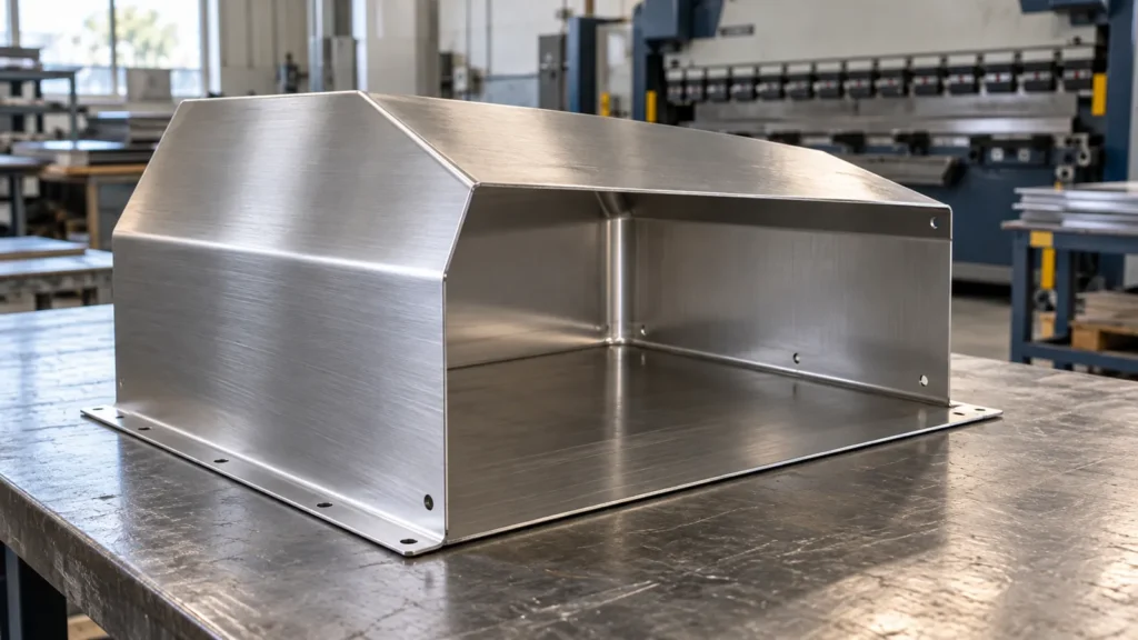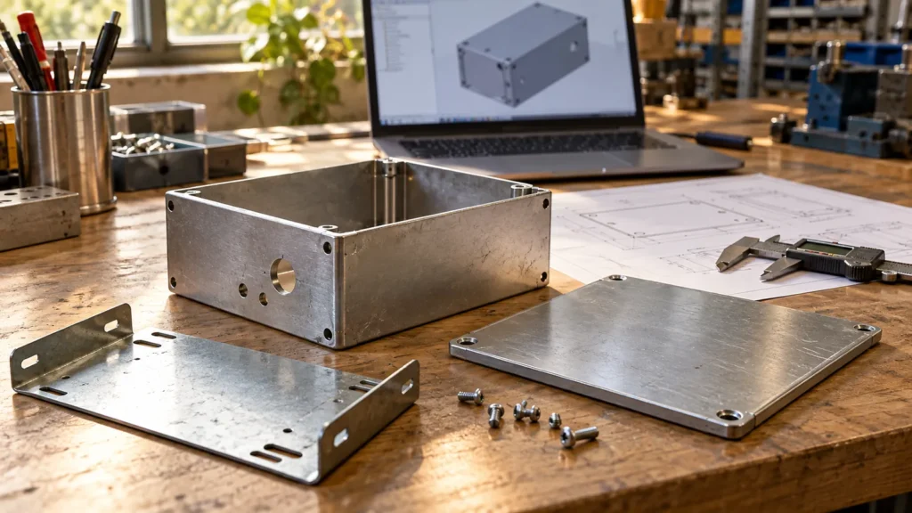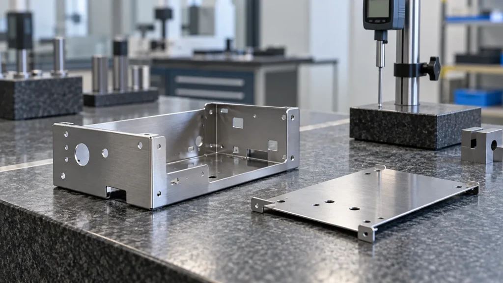
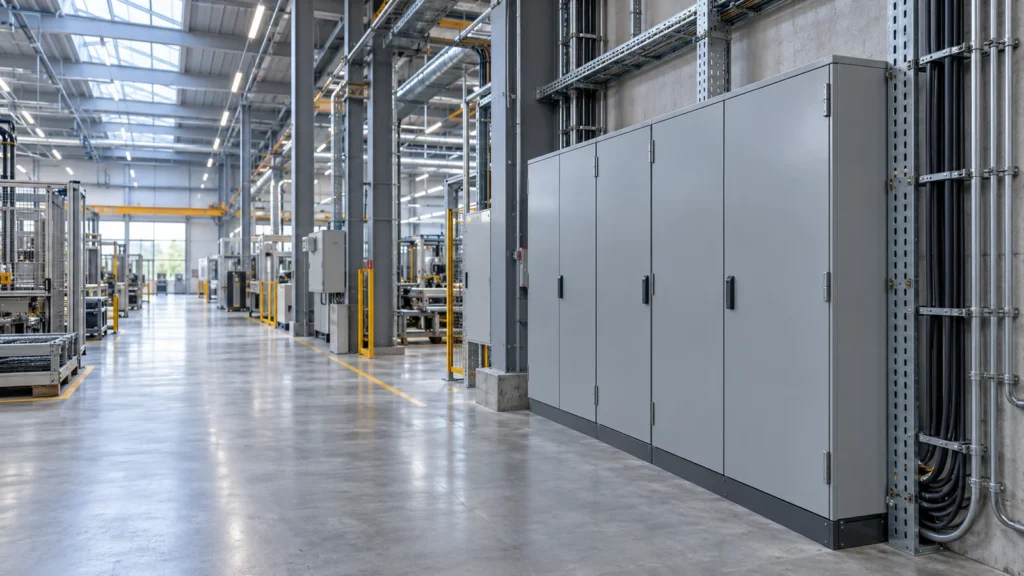
Sheet metal assembly brings cut and formed components together into a complete mechanical structure. It can involve welding, screws, rivets, installed hardware, brackets, hinges and removable panels. The best assembly method depends on the joint’s function, the materials involved and whether the product needs to be serviced.
For OEM buyers, assembly deserves attention early in design. A collection of acceptable individual parts can still create a difficult build if their interfaces, clearances or installation sequence have not been coordinated.
Fabrication and Assembly Have Different Checks
Fabrication establishes the geometry of individual components. Assembly checks how those components work together.
A panel may have the correct outside dimensions but interfere with a neighboring flange. A mounting plate may fit inside a cabinet while leaving insufficient space for a tool. A door may close before coating and rub against the frame afterward.
| Stage | Main question |
|---|---|
| Individual part fabrication | Does the part meet its drawing requirements? |
| Hardware installation | Is the specified hardware correctly located and retained? |
| Mechanical assembly | Do the parts fit, operate and remain accessible? |
| Final inspection | Does the complete assembly meet the agreed acceptance criteria? |
An assembly drawing should therefore communicate the relationship between parts, not simply show their arrangement.
Review the Assembly, Not Only the Individual Parts
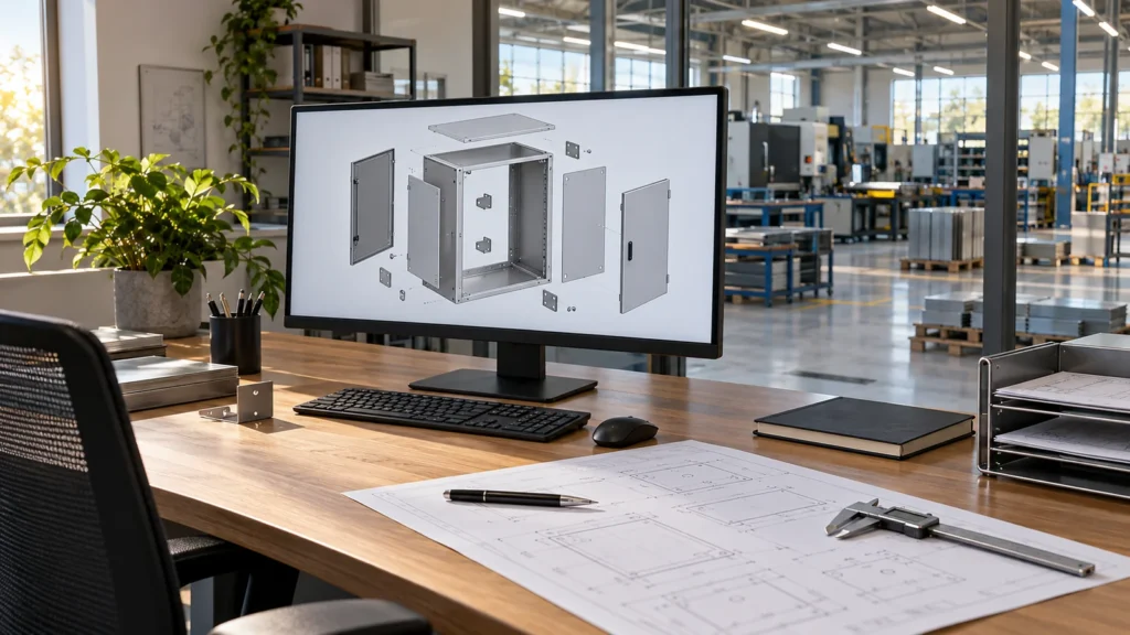
Begin with the interfaces that determine function.
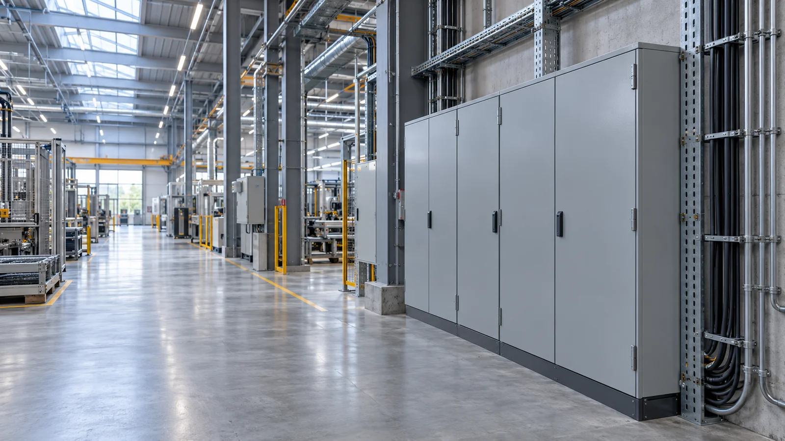
For a control cabinet, these may include the mounting plate, door opening, hinge positions and cable-entry areas. For a lighting housing, they may include the optical component envelope, support bracket and removable service cover.
Mark the surfaces and holes that locate each component. Then distinguish them from features that provide general clearance or appearance.
A 3D assembly model is useful for checking:
- Component interference.
- Door and cover movement.
- Fastener and tool access.
- Installation direction.
- Clearance around mating equipment.
- Removal of serviceable parts.
Also consider the product in its installed position. A screw that is accessible on the workbench may become difficult to reach after the assembly is mounted against a wall.
Choose a Joining Method for Each Interface
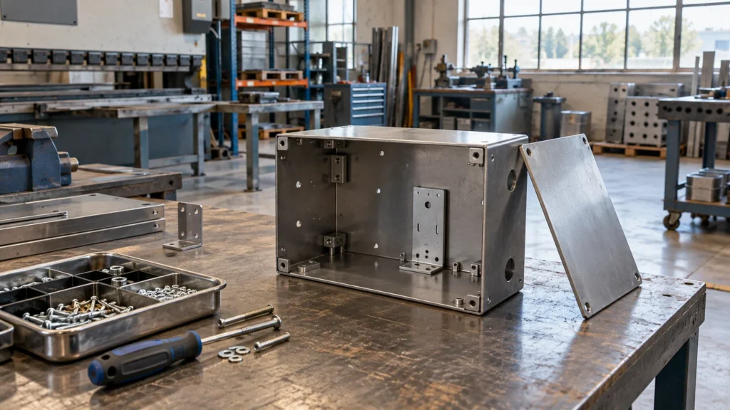
Different joints within one product can require different methods.
Welding
Welding can create permanent connections between compatible components. Joint access, fixturing, heat input, distortion and surface appearance should be reviewed. The drawing should make weld requirements clear and identify any surfaces that need subsequent finishing.
Screws and bolts
Threaded fasteners suit joints that need assembly, adjustment or later removal. Their design requires adequate tool clearance, a defined fastening interface and suitable access for replacement.
Rivets
Rivets can be useful where a permanent mechanical joint is appropriate. Review access to the joint, material compatibility and the implications for future disassembly.
Self-clinching hardware
Self-clinching nuts, studs and standoffs can provide fastening features in sheet metal. Selection depends on the specific fastener, sheet thickness, sheet hardness, mounting hole and edge distance. Follow the hardware manufacturer’s installation instructions rather than applying one rule to every insert. PennEngineering installation guidance
The choice should be documented for each important joint. Leaving the method open can affect the fabrication route, finishing sequence and inspection plan.
Control the Features That Locate the Assembly
Tolerance decisions should start with the finished function.
Consider a removable mounting plate inside a cabinet. The plate’s outside profile, support positions and fastening holes all contribute to fit. Tightening every dimension may add cost without improving installation. Instead, identify which dimensions establish the interface and how they relate to one another.
Useful questions include:
- Which component establishes the main reference?
- Does one hole locate the part while another allows adjustment?
- Can variation in several bends affect the final mounting position?
- Will coating alter the clearance at a close-fitting joint?
- Can a fixture reproduce the required relationship during joining?
Locating tabs, slots or controlled reference holes may help position parts, but they must also be manufacturable. Review them alongside the cutting and forming requirements.
Agree the Assembly and Finishing Sequence
The sequence should account for access and the selected hardware.
Some hardware installation or joining operations need to happen before the enclosure becomes difficult to reach. Other components may be installed after finishing to protect the coating or preserve serviceability.
For self-clinching fasteners, the panel surface and finishing sequence are particularly important. PennEngineering advises against installation on pre-painted surfaces and stresses appropriate installation force and edge distance. Manufacturer’s installation instructions
The production plan should identify:
- Part preparation and reference checks.
- Forming and any required trial fitting.
- Hardware installation and permanent joining.
- Surface preparation and finishing.
- Installation of remaining mechanical components.
- Final fit, operation and appearance checks.
The exact order must be adapted to the design. Zhen Pai’s welding and assembly services support this discussion alongside fabrication requirements.
Keep the Drawing Package Consistent
A clear bill of materials connects the finished assembly to its individual components.
Include part numbers, quantities and drawing revisions. Identify purchased hardware separately from fabricated parts. Where several versions share a common enclosure, make their different holes, mounting features or components clear.
Before production, resolve conflicting information between the 3D model, component drawings and assembly drawing. Also agree how an engineering change will be communicated and approved.
For buyers sourcing custom sheet metal parts, this makes the inquiry easier to review and helps define what the supplier is expected to deliver.
Inspect the Complete Mechanical Assembly
Final inspection should include the functions affected by assembly.
Depending on the product, checks may cover door movement, removable panel fit, mounting positions, hardware retention, overall geometry and visible finish.
Where a mating component is critical, agree whether an actual component, representative fixture or defined dimensional check will be used. Include required records in the quotation request.
Mechanical inspection does not establish electrical performance or an environmental protection rating. Those requirements need their own defined verification scope.
See Zhen Pai’s quality control page for information about drawing-based inspection planning.
Frequently Asked Questions
Is welding always required for sheet metal assembly?
No. Screws, rivets and installed hardware may suit some joints. The decision depends on load, access, appearance, material and maintenance requirements.
Should all parts be finished before assembly?
The sequence varies. Permanent joining, hardware installation, coating and final fastening must be coordinated. Follow the requirements of the finish and hardware manufacturer.
What should I send for an assembly quote?
Provide component drawings, an assembly drawing or model, a bill of materials, hardware specifications, finish requirements and quantity. Identify critical interfaces and the required inspection scope.
Plan Your OEM Assembly with Zhen Pai
Zhen Pai provides sheet metal design, 3D modeling and manufacturing from customer drawings. Send your assembly files or design brief to discuss joining methods, fabrication requirements and the approval steps needed before production.