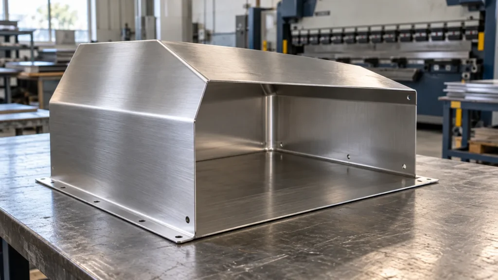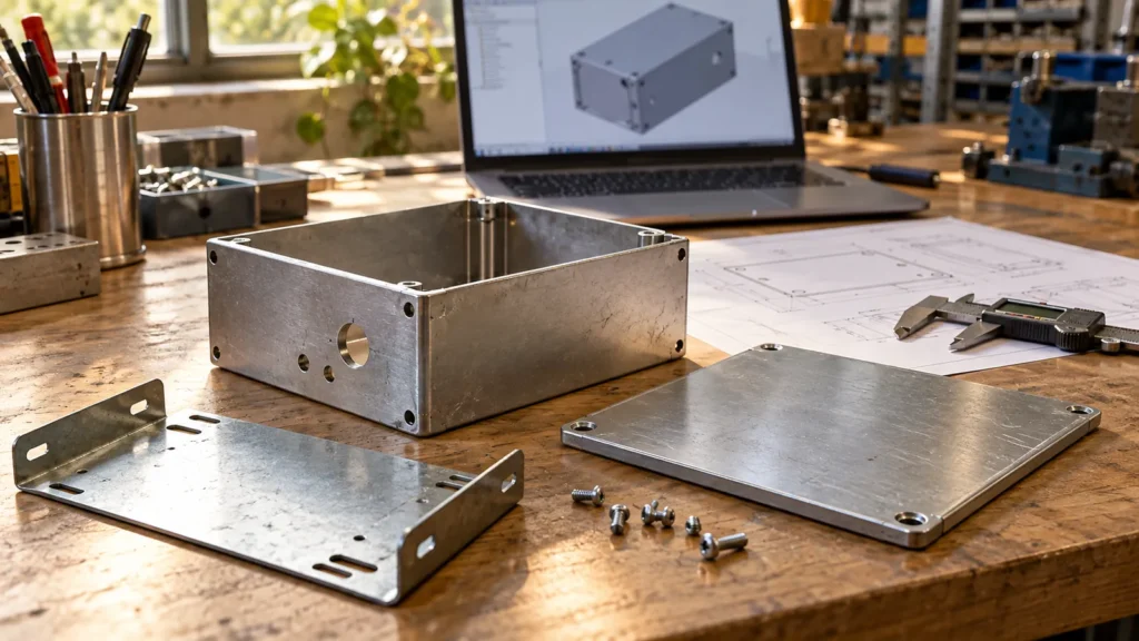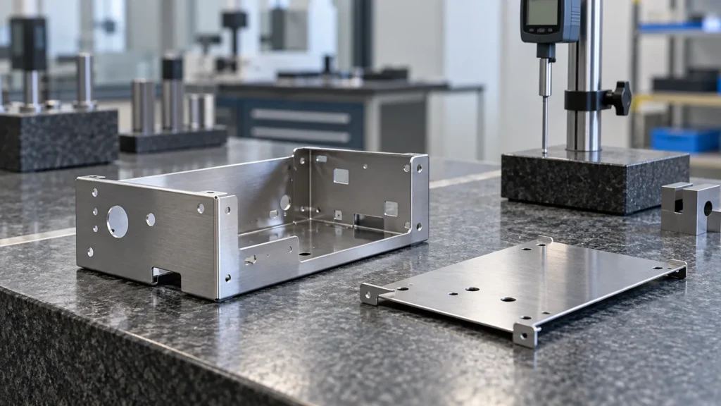

Imagine a technician replacing a board inside a small control unit. The cover comes off easily, but the mounting screws sit behind a cable bundle. Removing the board means disconnecting a neighboring component that was supposed to stay in place. The enclosure fits everything on the drawing; servicing it tells a different story.
Custom enclosure design should account for those moments before the outline is fixed. Component space, access, cable routes, and mounting interfaces belong in the same mechanical review. A neat exterior cannot compensate for an assembly that becomes awkward once it is wired.
Design the removal path, not just the packed volume
Component envelopes tell you whether parts fit inside the enclosure. They do not tell you whether those parts can enter or leave it.
Review installation and service as separate sequences. A board may slide into an empty chassis during assembly but be blocked by a harness during replacement. A removable cover may clear the enclosure itself while colliding with the machine on which it is mounted. A connector can be accessible to a finger yet inaccessible to the tool needed to release it.
For a hypothetical controller, suppose the main board mounts horizontally below a terminal strip. A removable internal tray could allow the board to be withdrawn with its standoffs still attached. That option introduces its own fastening and cable requirements, but it is worth considering before the enclosure geometry is frozen.
Show tool space, connector engagement, and removal directions in the model. These need not all become tightly controlled dimensions. They do need to be visible to the people making layout decisions.
Be specific about the expected service setting. A unit opened on a workbench presents different access constraints from one fixed beside a production line. The intended arrangement should determine which faces remain reachable.
Give each face a job
An enclosure becomes easier to resolve when its surfaces have clear roles. One face might carry the mounting interface; another might provide field cable entry. A cover may carry no components at all, allowing it to come away without disturbing the harness.
This does not require a universal layout. It requires avoiding accidental dependencies. If a heavy connector mounts on a thin removable panel, for example, its fastening and cable forces must be considered alongside the panel’s fit and support. If a service label belongs on the inside of the cover, check whether it remains readable in the planned opening position.
Decide where the product is located in the enclosure. A mounting tray, standoffs, and enclosure walls should not all compete to locate the same board through incompatible dimensions. Establish the intended references, then give other connections the clearances the assembly needs.
At this stage, ZhenPai’s manufacturing services can be used to discuss the enclosure as a group of fabricated parts. A base, cover, tray, and bracket may each need a different forming or joining approach.
Treat bends as physical space
The sharp corner shown in a quick layout sketch does not exist in a formed sheet metal enclosure. The bend has an inside radius, an outside surface, and a region that changes during forming. Nearby hardware and cutouts must fit around that geometry.
Protocase’s enclosure design guide notes that flat mounting space begins beyond the bend region and that cutouts too close to a bend can deform during forming. Its guidance ties feature clearance to material, thickness, and tooling rather than a single value for every enclosure. Protocase: Electronic Enclosure Design 101
Include the actual bend geometry when checking a lid against a base. Two nominally matching edges can interfere if one design ignores the other’s formed corner. Fastener positions also need enough usable surface and installation access; clearance for a screw head is only one part of the connection.
Corner reliefs, short flanges, and closely spaced bends should be reviewed with the intended process. Avoid selecting a radius in isolation and then assuming the rest of the part can be made around it. ZhenPai’s bending and stamping capabilities are relevant to that manufacturability review.
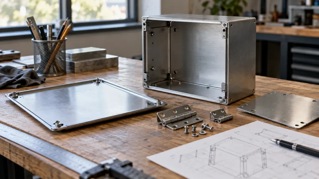
Separate mechanical provision from electrical verification
An enclosure drawing can define holes for grounding hardware, spaces for cooling components, and mounting features for connectors. Those provisions help the electrical design work. They do not establish electrical safety, electromagnetic compatibility, or thermal performance by themselves.
Agree who supplies each requirement and who verifies the assembled product. A useful division might look like this:
| Product requirement | Mechanical information needed |
|---|---|
| Grounding arrangement | Hardware locations, contact surfaces, and finish requirements defined by the electrical design |
| Connector installation | Approved cutouts, mounting pattern, and mating clearance |
| Cooling layout | Component locations, airflow paths, and space for the specified cooling hardware |
| Environmental protection | Joint geometry, sealing components, and acceptance requirements for the intended assembly |
The table is a coordination aid, not an approval checklist. For example, a ventilation opening might improve a proposed airflow path while changing the enclosure’s protection requirements. That conflict needs a product decision, followed by the relevant verification.
Keep finish requirements connected to the interfaces. If the electrical design calls for a particular contact surface, identify it on the controlled documentation. “Paint enclosure” is too broad when some areas have a different function.
Do not assign an IP or NEMA rating from appearance. A closed cover, gasket, or overlapping flange does not demonstrate a rating. The complete enclosure arrangement needs the applicable evaluation before any such claim is used.
Let the cover support the intended work
A cover can lift off, slide out, or remain attached on hinges. Choose the arrangement by following the service task.
A lift-off lid may be convenient on a bench but need a safe place to rest at the installed location. A hinged door may keep the panel attached but require swing clearance. If components mount on the door, their cables need an appropriate path through the opening movement. Sliding covers need room to travel before they disengage.
Captive fastening may be useful where loose hardware is inconvenient, but the selected hardware must suit the sheet and the design. Document access to its installation and replacement. A convenient service feature can become a production difficulty if no one checks the manufacturing sequence.
Also decide what an operator is allowed to open and what requires a service procedure. The mechanical layout should support the product’s access requirements. Locking or fastening choices belong to that wider design brief.

A hypothetical layout review
Consider a wall-mounted monitoring unit with a main board, power module, and removable lower cable-entry plate. In the initial layout, the power module sits immediately behind the entry plate. The enclosure is compact, but cable installation blocks access to one module screw.
One revision could move the power module onto an internal tray and route field cables through a separate lower channel. Another could move the entry plate to a side face that remains accessible at installation. Neither choice is automatically better. The available wall space, connector arrangement, service frequency, and manufacturing plan decide the tradeoff.
The review should answer a concrete question: can the module be replaced in the intended installation without removing unrelated components? Confirm it using the current component geometry and an agreed service sequence. If a physical sample is needed, define which access conditions it must demonstrate.
That review is more useful than adding empty volume throughout the enclosure. Clearance placed where the work happens can solve the problem without making every face larger.
Send a design package that describes use
A quotation package should include component models or controlled envelopes, connector details, mounting requirements, material and finish preferences, and the enclosure’s installation arrangement. State expected quantities and identify any dimensions or interfaces already fixed by the product.
Add a short description of assembly and service access. If the design requires testing, specify the relevant requirements and responsibilities. Keep those requirements distinct from assumptions about what the fabrication will achieve.
ZhenPai offers design and 3D modeling alongside production from customer drawings. Review the available capabilities and send the enclosure requirements with the component layout. A usable enclosure begins with a clear account of the work people need to perform inside it.