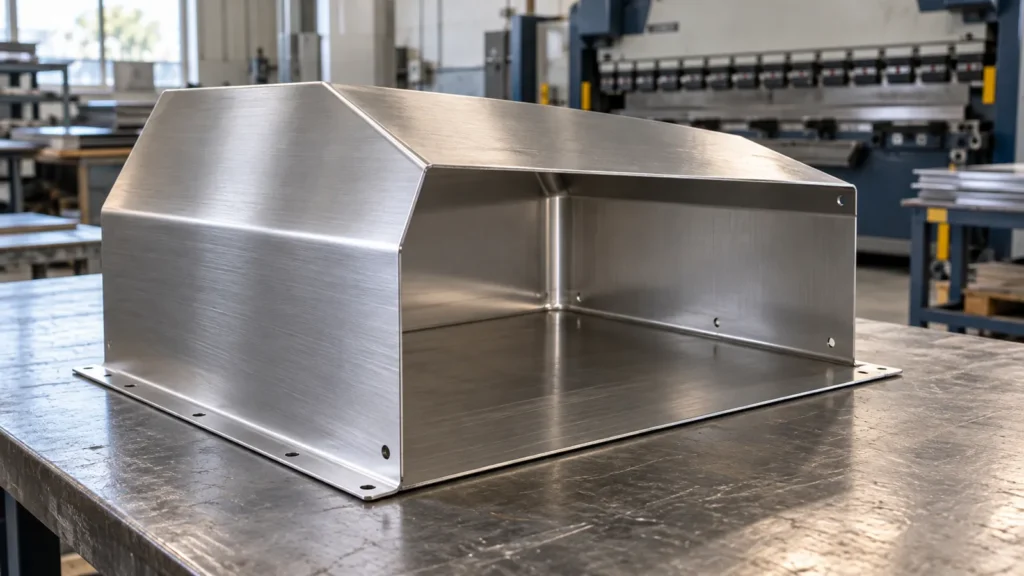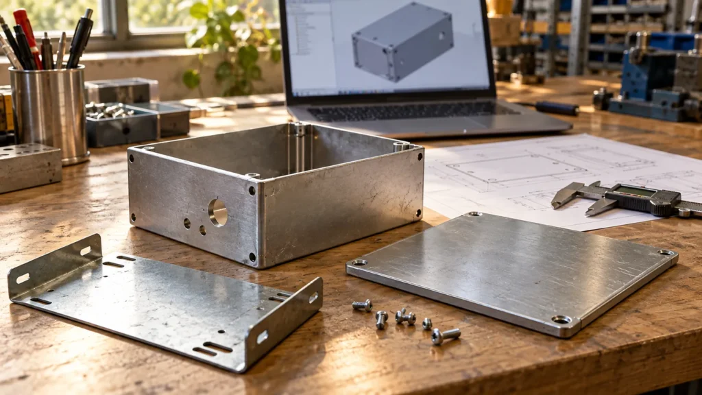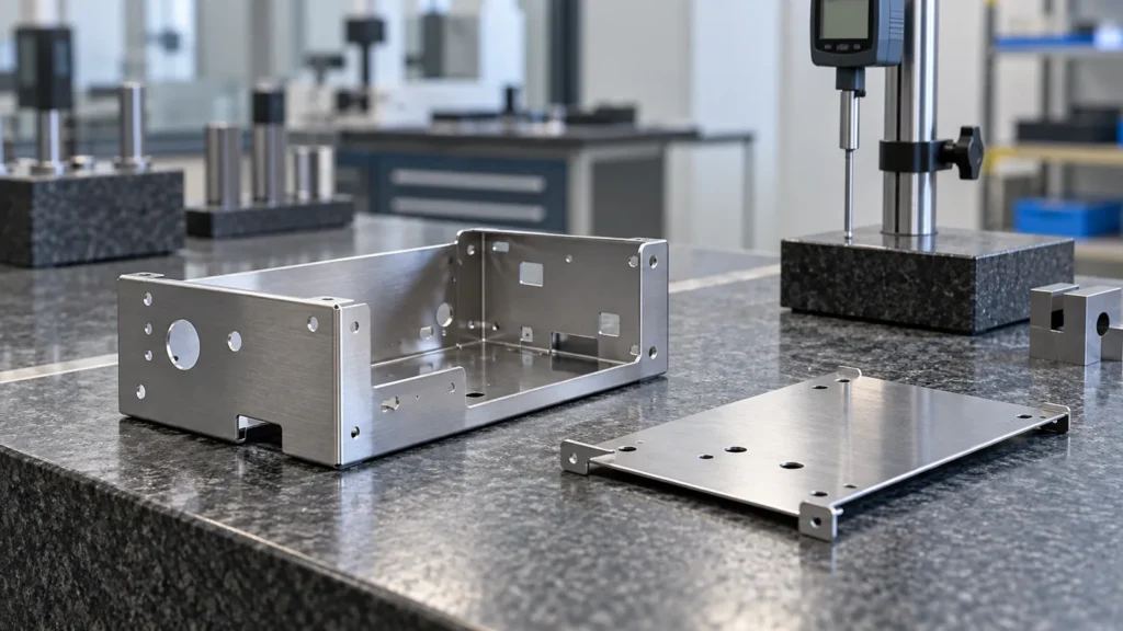

A mounting bracket can pass every dimension on its drawing and still fail to fit the equipment. The problem may be a hole measured from the wrong edge, an unchecked bend angle, or a finish allowance nobody included in the clearance. Sheet metal engineering comes down to resolving those relationships before production starts. A neat drawing helps, but the release review has to ask a harder question: does this package tell the fabricator what the finished part must do?
For an OEM buyer, the most useful review follows the part through manufacture and into its installed position. It starts with function, then tests the drawing against the proposed operations and inspection method.
Start with the surfaces that locate the part
Imagine a folded support that bolts to a machine frame and holds a sensor. Its outside edges provide a convenient way to describe the shape. They may have very little to do with the sensor position, however. The mounting face, the bolt pattern, and the sensor seat control how the support works.
Mark those interfaces first. Which face sits against the frame? Which feature fixes the lateral position? Is the sensor aligned by a hole, a slot, or the assembly fixture? The answers should guide the datum scheme and the dimensions called out as critical. Measuring everything from a free edge because it is easy to find in CAD can hide the relationship that matters in the machine.
Do not turn every dimension into a critical dimension. That makes the review harder without explaining priority. A useful drawing distinguishes functional requirements from the dimensions that simply describe the remaining shape. It also gives the fabricator room to choose a sensible process for features that do not affect fit.
Read the drawing and model as a pair
A solid model communicates shape well. It is less reliable as a complete description of surface condition, inspection expectations, or acceptable manufacturing variation. Protolabs identifies grain direction, hardware details, and secondary operations as information that a 2D drawing can communicate alongside a CAD model. Protolabs technical-data guidance
Before release, check that the model and drawing show the same revision. Compare material, thickness, hole sizes, bend directions, and handed features. An old PDF attached to a new STEP file creates two plausible instructions. The shop should not have to choose between them.
State which document controls if a discrepancy appears. A formed part model might define the nominal geometry while the drawing supplies tolerances and finish notes. If a supplied flat pattern is for reference, label it accordingly. If it is mandatory production data, explain that requirement and have the manufacturer review it before the order is released.
This division needs to be agreed with the supplier. A flat pattern generated with one bending assumption may require adjustment for a different forming route. Treating the CAD export as unquestionable can move the error into every finished part.
Check dimensions across bends separately
A hole pattern on one flat face and a distance across two folded walls present different manufacturing questions. The second involves the cut geometry, bend position, bend angle, and how the part is held during measurement. They deserve separate attention during the drawing review.
Return to the sensor support example. The mounting holes could be correct relative to each other while the sensor seat is tilted. Adding a tighter hole tolerance would not fix that condition. The review needs to connect the seat position and orientation to the mounting interface, then agree how those relationships will be checked on the formed part.
Ask whether a dimension is intended to apply in the free state or after fastening. A cover with a little elastic movement may settle into its intended shape when installed. A locator bracket may need to hold its position before assembly. Those are different acceptance conditions, and the drawing should make the distinction clear.
Discuss demanding requirements with the manufacturer before assigning a number. Zhen Pai’s bending and stamping information is a useful starting point for identifying the forming operations in a custom part. The tolerance commitment for a particular drawing still needs to be confirmed for that part, material, and process.
Look for features that change during manufacture
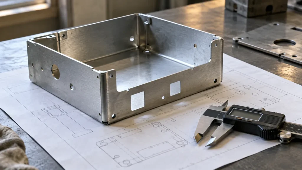
The release review should walk through the likely operation sequence. Start with the blank. Check narrow sections, small cutouts, and the position of functional holes. Then look at the formed state. Can the tooling reach each bend? Does a return flange obstruct a later operation? Is a hole so near a bend that its shape or location deserves a specific review?
For a welded component, carry the same questions beyond the individual pieces. A dimension that is easy to check before joining may be difficult to reach afterward. A surface used for location could be obscured by a weld or require finishing. Show the relevant weld locations and identify any interfaces that must retain their geometry through the joining sequence.
This is a good reason to review welding and assembly requirements together with the component drawings. The finished assembly needs its own acceptance logic. A set of acceptable loose parts does not automatically establish acceptable fit after joining.
Keep process discussions specific. “Please optimize the design” leaves too much open. “This hole locates the sensor; moving it is not permitted, but the adjacent flange length can change” gives the manufacturer a useful boundary.
Give the finish a place in the dimensional review
Finish notes often receive attention after geometry is settled. That is too late when they affect mating surfaces, threads, or appearance. Name the finish, identify the surfaces involved, and say whether dimensions apply before or after it is added.
A sliding panel illustrates the issue. Its nominal width may leave enough space in the opening, yet the accepted combination of panel width, opening width, and finished surface condition could make it bind. Review the available clearance at the limiting conditions rather than checking only the nominal CAD fit.
Separate cosmetic and functional surfaces. An exposed front face may need an agreed appearance, while a hidden mounting face needs flat contact and clean fastener access. If directional grain must continue across adjoining parts, show the direction. If a surface must be protected from handling marks, identify it in a view that the shop can use.
For appearance requirements, an approved physical sample or a well-defined visual reference is usually more useful than an adjective. “Good finish” and “smooth edge” do not describe the same result to every reviewer.

Make inspection possible before you ask for a report
Choose an inspection approach that answers the functional questions. A basic hole check may be enough for one feature. A formed relationship may call for a fixture, a defined support condition, or a measurement from selected datums. Agree those details during release, especially when the part can flex under measuring pressure.
Decide what the first sample must demonstrate. It might need to mount to a mating part, accept specified hardware, and meet a short list of recorded dimensions. An inspection report full of easy measurements can miss the one relationship that stops assembly. Zhen Pai’s quality control page provides context for that conversation; the inspection scope for the order should be stated explicitly.
Close the review with a single, identifiable release package. Include the revision, controlled drawings and models, material and finish requirements, quantities, and the agreed treatment of open questions. Keep approved changes in that package rather than scattering them across messages.
If a custom component is ready for review, send the drawing and mating requirements to Zhen Pai. Identifying the locating surfaces and critical relationships gives the discussion a practical starting point before production is agreed.