Equipment & Production
Equipment that supports repeatable production.
Cutting and forming systems connected by disciplined setup, material control and first-article verification.
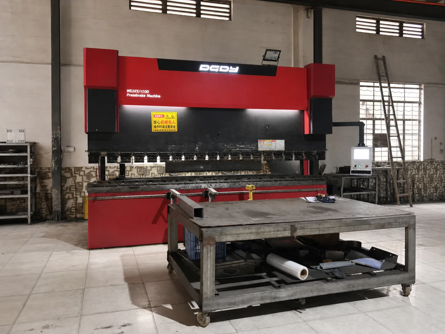
More than a machine list
Installed equipment, organized around the part.
Buyers need more than model names. They need to understand how equipment, operators and quality checkpoints work together.
Our production approach links drawing review, machine setup, part identification and inspection into one practical manufacturing route.
Production floor
Equipment in context.
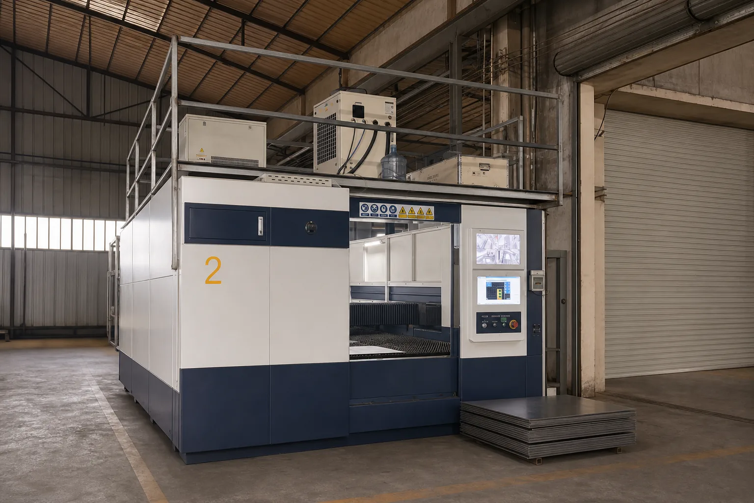
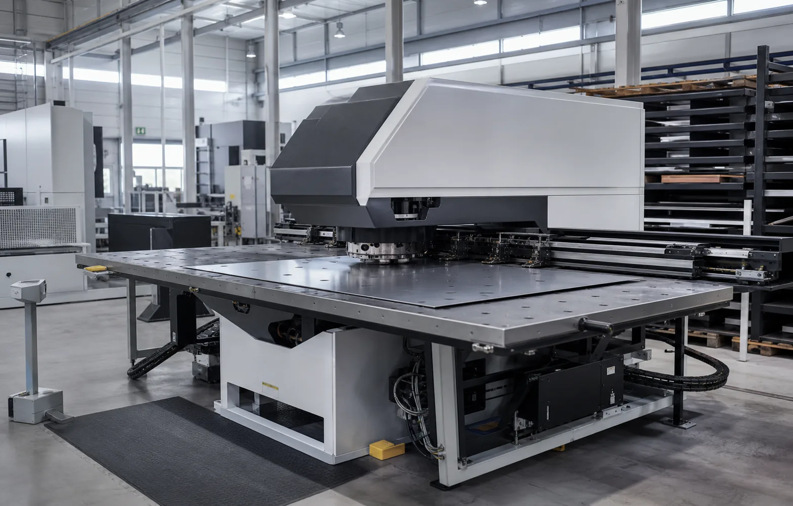
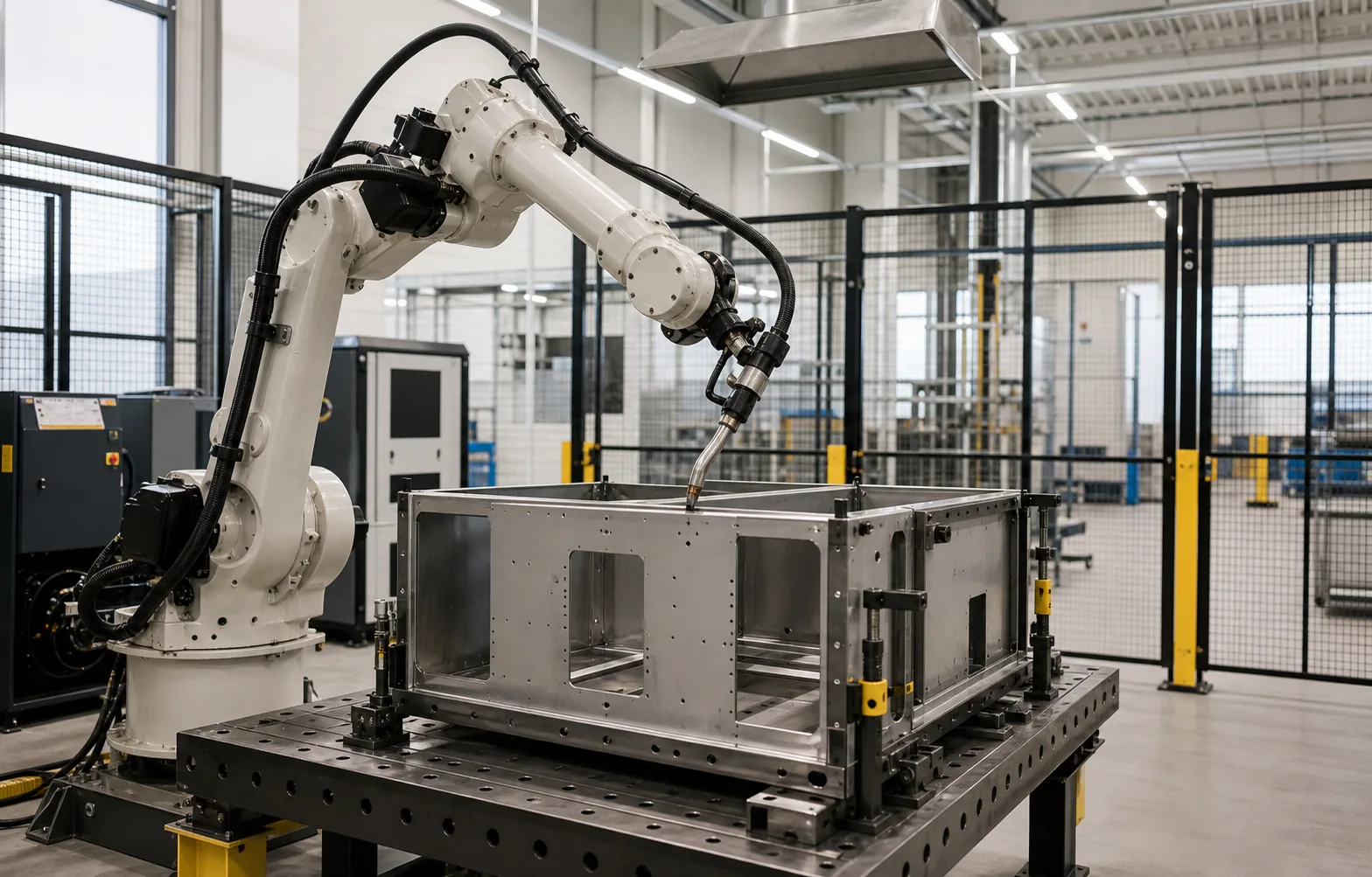
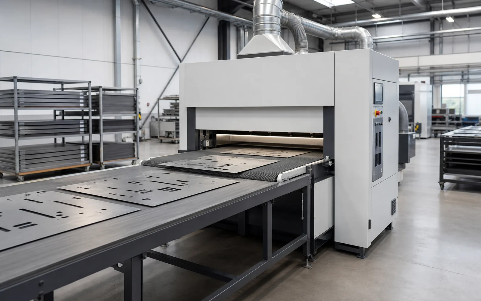
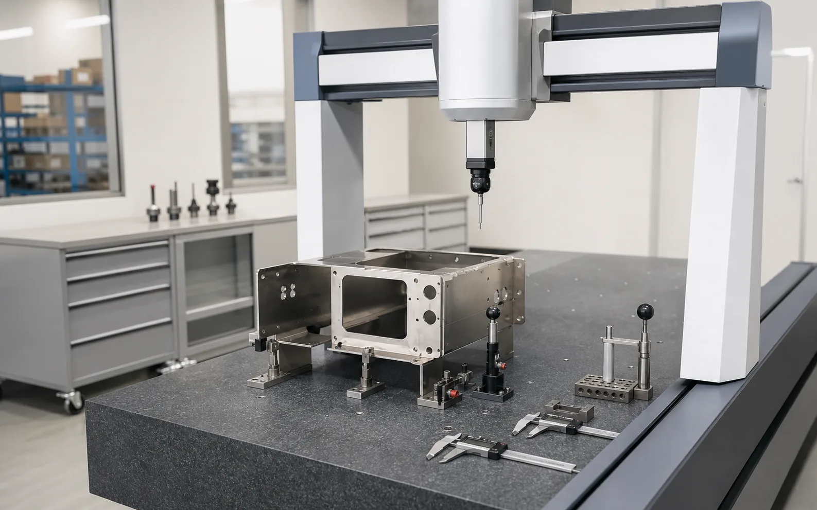
Explore verified factory photography alongside clearly labelled process visuals for complementary sheet metal operations.
Connected capability
Machines connected by process control.
Equipment creates value when drawings, tooling, materials and inspection standards remain aligned.
Cutting systems
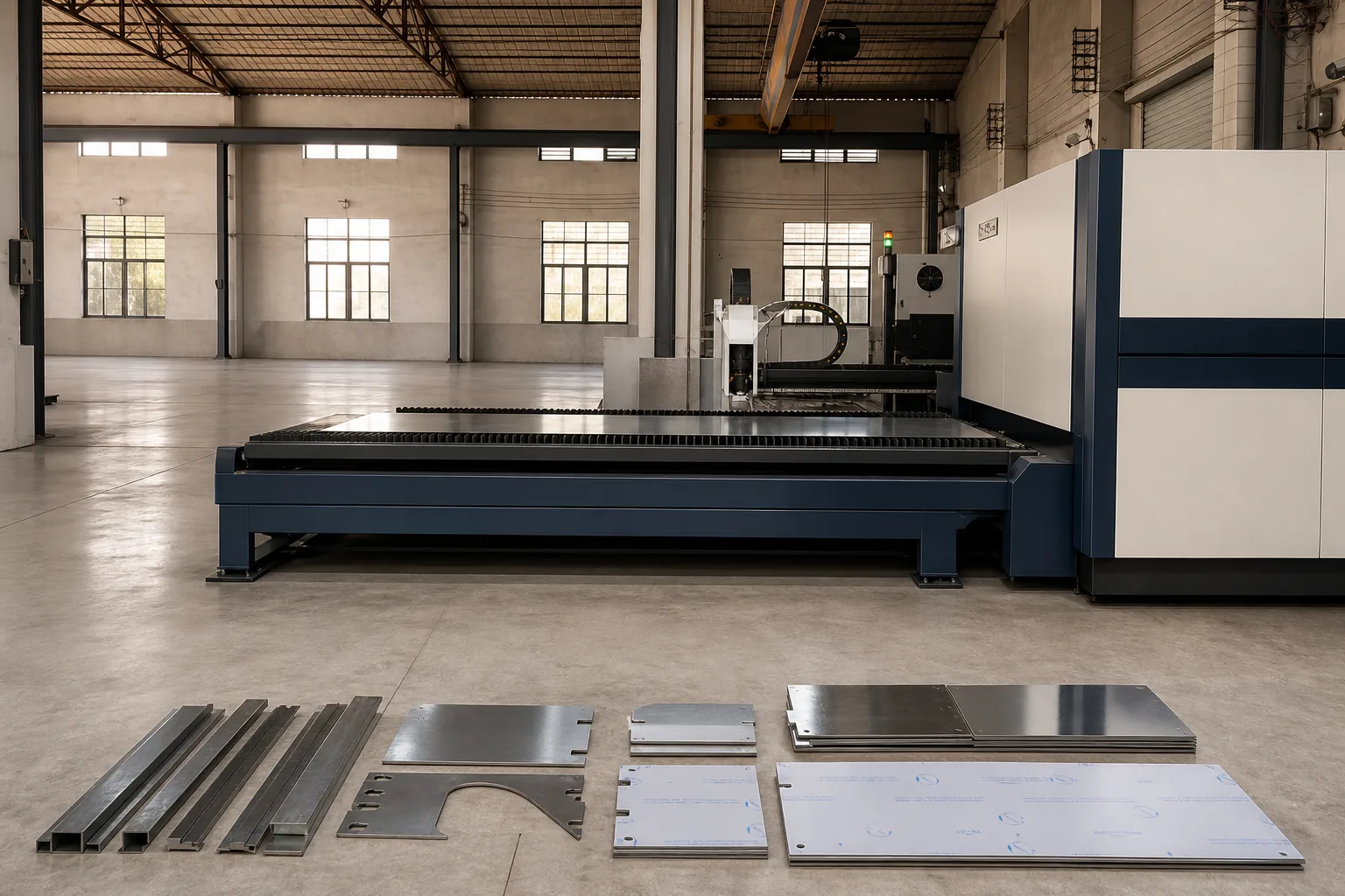
CAD-driven profiling, nesting and controlled part separation for downstream work.
Cutting capability ↗Forming systems
Programmed bend sequences and tooling selected around part geometry and interfaces.
Forming capability ↗Assembly support
Parts flow into welding and assembly with datums, orientation and fit requirements identified.
Inspection support
First-article and in-process checks connect machine output to the approved drawing.
Machine to part
The outcome matters more than the specification sheet.
Equipment selection is reviewed against the component itself: geometry, material, tolerance, cosmetic requirement and the next production operation.
- ✓ Drawing revision confirmed
- ✓ Material and thickness verified
- ✓ First article checked
- ✓ Parts identified for handoff
Capacity confirmation
Specific capacity is confirmed against your drawing.
Instead of publishing incomplete or misleading headline numbers, we confirm the machine route against the actual project requirements.
- Part envelope
- Overall size, geometry and handling requirement
- Material
- Grade, thickness, finish and grain direction
- Critical features
- Datums, tolerances, holes, bends and interfaces
- Production volume
- Prototype quantity, batch size and annual demand
- Process route
- Cutting, forming, welding, finishing and inspection
Start with the requirements
Need to confirm equipment fit for your project?
Send the drawing, material, tolerance and expected volume. We will review the production route and identify the relevant equipment.