
Welding & Assembly
Welded and assembled around fit, alignment and repeatability.
From individual brackets to complete enclosures, the process is planned around joint access, heat control and the way the finished assembly must function.
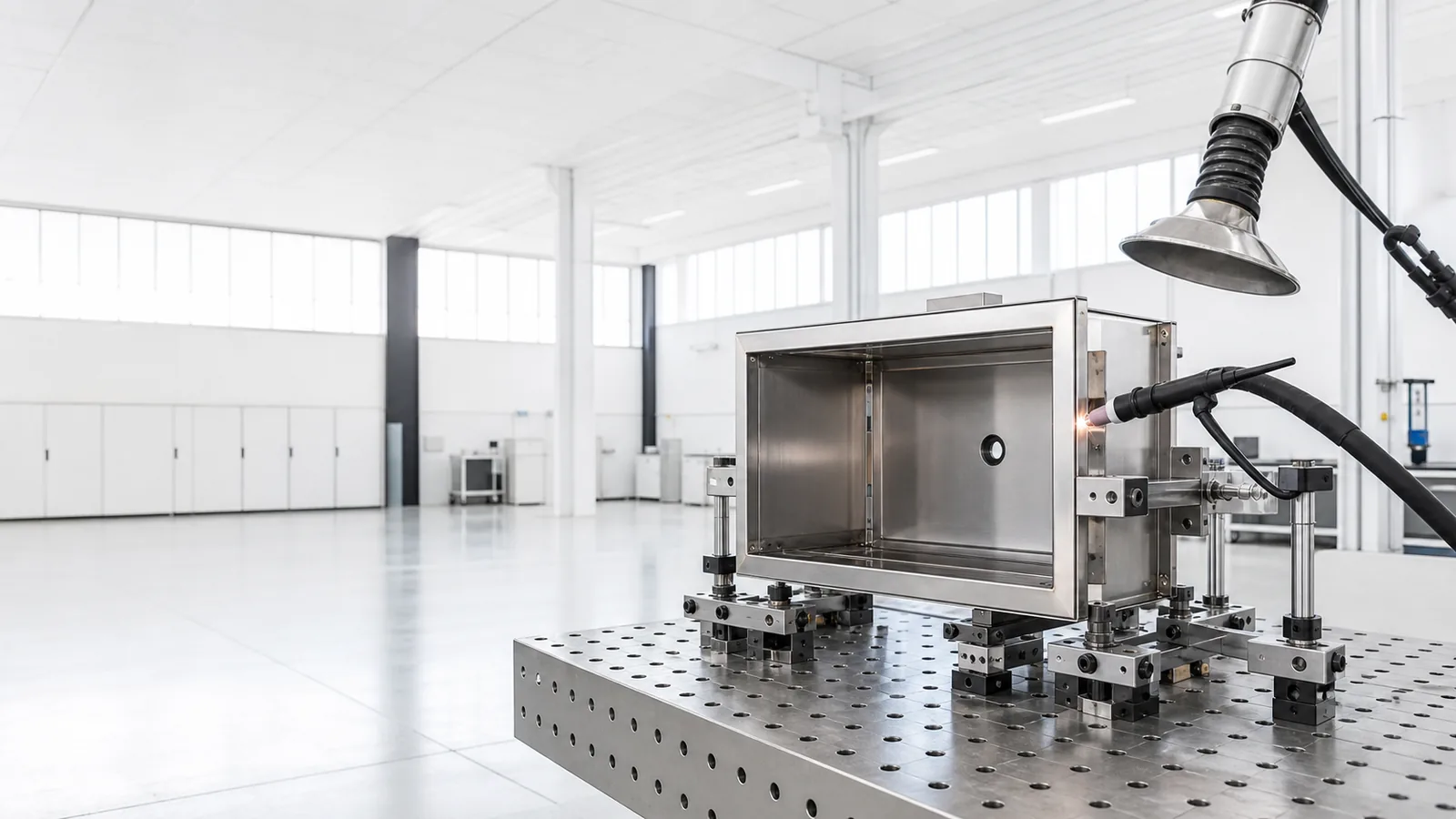
Before welding
A stable assembly begins before the arc is struck.
Welding can pull a precise sheet metal part out of shape. We review geometry, joint design, visible surfaces and downstream assembly before deciding the fixture and weld sequence.
The aim is practical: preserve the interfaces that matter while keeping the production route repeatable.
Joint access
Confirm tool access, seam position and finishing needs before parts are locked into the fixture.
Datums & interfaces
Protect mounting faces, door openings, panel edges and other features that control final fit.
Heat sequence
Plan tack locations and weld order around material, thickness, joint length and distortion risk.
Finish route
Coordinate grinding, brushing, coating and post-weld handling with the required appearance.
Production route
One connected route from parts to assembly.
The exact sequence depends on the drawing and finish. These six stages show how welding and assembly stay connected to dimensional control.
- 01
Prepare
Part review
Revision, material, bend condition and joint edges checked before fit-up. - 02
Position
Fixture & tack
Components located from defined datums and held for repeatable alignment. - 03
Join
Controlled welding
Process and sequence selected around material, strength and heat input. - 04
Correct
Finish & straighten
Required seam finishing and dimensional correction completed before coating. - 05
Build
Mechanical assembly
Hardware, doors, panels and internal components installed as specified. - 06
Release
Final verification
Dimensions, fit, function and appearance reviewed before packing.
Process explorer
See how control changes through the build.
Select a stage to review the manufacturing priorities typically considered for welded sheet metal assemblies.
Stage 01
Alignment is established before the first weld.
Datums, access points and clamp sequence are planned around the drawing so the assembly can be held square while heat is introduced.
- Drawing datums and interface points
- Joint access and clamp sequence
- Repeatable positioning for batch work
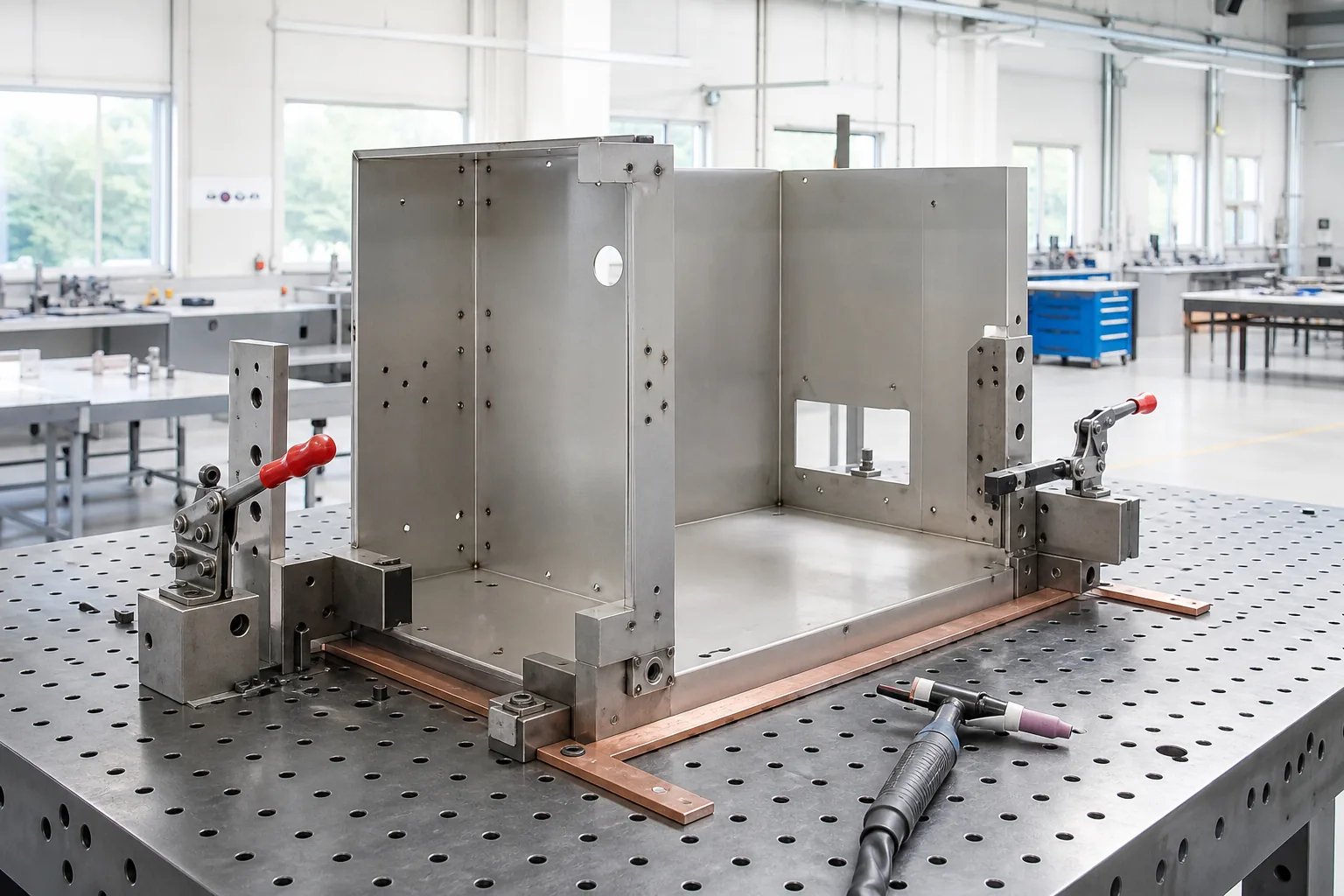
Stage 02
The weld sequence is matched to material and geometry.
Joint fit-up, tack pattern, heat input and finishing route are selected to support strength, appearance and dimensional stability.
- Tack and weld sequence
- Heat and distortion management
- Visible seam and finishing requirement
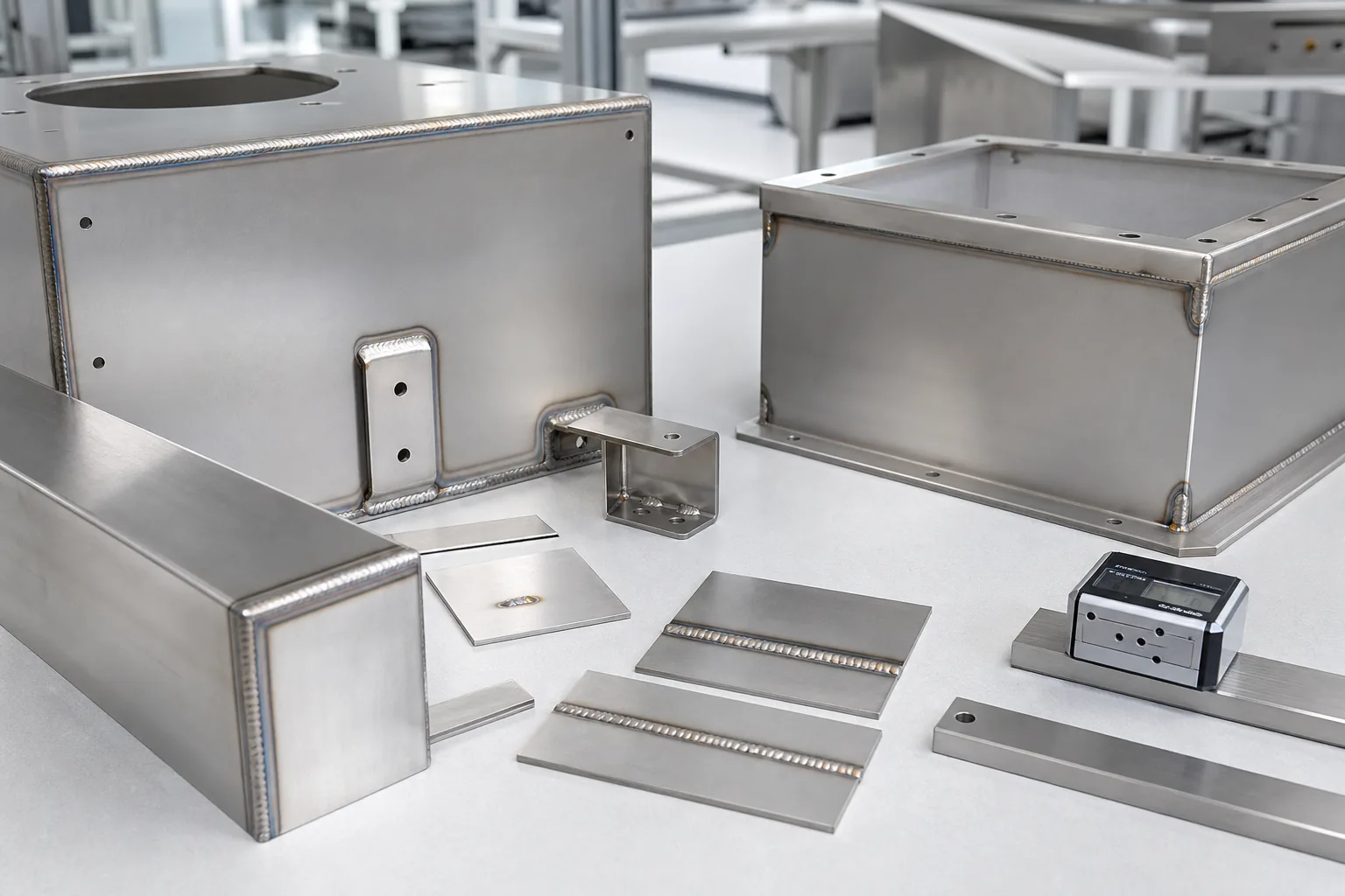
Stage 03
Hardware, panels and interfaces brought together in one build.
Mechanical components can be assembled after fabrication and finishing so fit, access and part relationships are checked before packing.
- Doors, hinges and removable panels
- Fasteners, inserts and mounting hardware
- Fit, function and final visual review
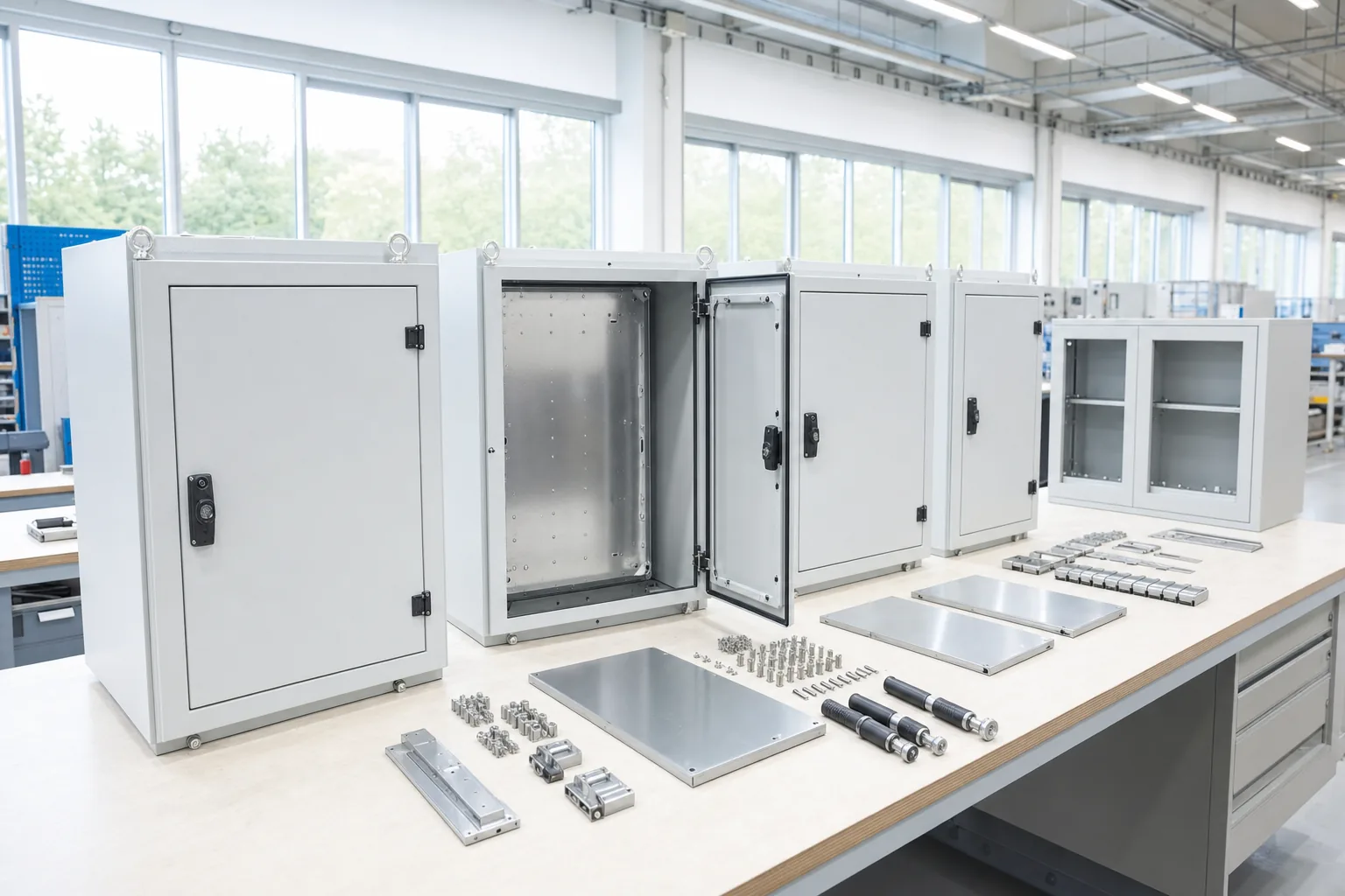
Material considerations
The joining route changes with the material and finish.
Process selection is confirmed from the drawing. These are common considerations rather than fixed specifications.
Stainless steel
Clean fit-up, surface protection, heat control and seam appearance for visible or corrosion-sensitive assemblies.
- Enclosures and housings
- Brackets and trays
- Visible welded assemblies
Carbon steel
Joint preparation, fixture support and post-weld finishing coordinated with structural needs and coating.
- Frames and bases
- Equipment housings
- Powder-coated assemblies
Aluminum
Clean handling, controlled fit-up and suitable joint access for lightweight fabricated assemblies.
- Lightweight covers
- Panels and housings
- Custom support structures
Assembly integration
Reduce the number of handoffs after fabrication.
Where the project requires it, fabricated parts can be brought together with mechanical hardware and checked as an assembly before shipment.
Installed hardware — inserts, studs, nuts and specified fasteners
Access components — hinges, doors, covers and removable panels
Internal interfaces — brackets, rails and mounting plates
Functional review — alignment, access and mechanical operation
Inspection points
Verify the assembly, not only the weld.
Final checks are based on the drawing and agreed requirements. The goal is to protect the interfaces the customer will use.
Overall geometry
Squareness, flatness and critical assembly dimensions.
Weld condition
Location, continuity and visible appearance as specified.
Interface alignment
Doors, panels, mounting points and mating features.
Hardware function
Fastener seating, access and mechanical operation.
Start with the assembly drawing
Show us how the parts need to fit and function.
Share the CAD files, material, visible-surface requirements, critical interfaces and estimated volume. We will review the fabrication and assembly route.